01. Project Overview
Project Overview
The following video will provide an overview of the project. You can find the project starter code in the
Radar_Target_Generation_and_Detection.m
file in the
Resources
section of the classroom. Additionally, the project rubric can be found
here
.
Final Project Walkthrough

- Configure the FMCW waveform based on the system requirements.
- Define the range and velocity of target and simulate its displacement.
- For the same simulation loop process the transmit and receive signal to determine the beat signal
- Perform Range FFT on the received signal to determine the Range
- Towards the end, perform the CFAR processing on the output of 2nd FFT to display the target.
Radar System Requirements
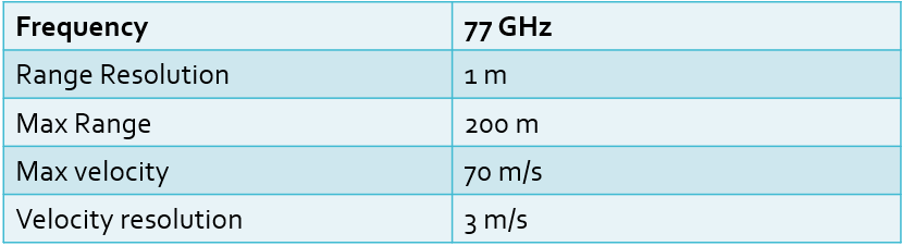
System Requirements defines the design of a Radar. The sensor fusion design for different driving scenarios requires different system configurations from a Radar. In this project, you will designing a Radar based on the given system requirements (above).
Max Range and Range Resolution will be considered here for waveform design.
-
The sweep bandwidth can be determined according to the range resolution and the sweep slope is calculated using both sweep bandwidth and sweep time.
Bandwidth (B_{sweep}) = speed \,\, of\,\, light/(2*rangeResolution)
-
The sweep time can be computed based on the time needed for the signal to travel the unambiguous maximum range. In general, for an FMCW radar system, the sweep time should be at least 5 to 6 times the round trip time. This example uses a factor of 5.5.
T_{chirp} =5.5\cdot 2 \cdot R_{max}/c
Giving the slope of the chirp signal
Slope = Bandwidth/T_{chirp}
Initial Range and velocity of the Target
You will provide the initial range and velocity of the target. Range cannot exceed the max value of 200m and velocity can be any value in the range of -70 to + 70 m/s.